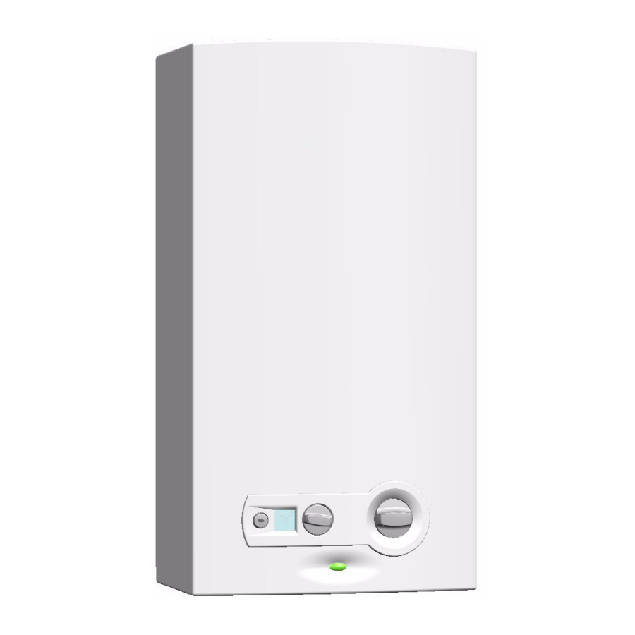

W Water gas heater
R Proportional power adjustment
D Digital display
11 Capacity (l/min)
-2 Version 2
B Electronic ignition powered by 1.5 V batteries
23 Indicator number of natural gas H
31 Indicator number of LPG
S. Country code
Operating convenience, as the heater is ready to operate by simply pressing a switch.

Fig. 1
| Dimensions (mm) | A | B | C | D | E | F | G | H (Ø) | |
| Natural gas | LPG | ||||||||
| WRD11B | 310 | 580 | 228 | 110 | 463 | 60 | 25 | 3/4" | 1/2" |
| WRD14B | 350 | 655 | 228 | 130 | 510 | 95 | 30 | 3/4" | 1/2" |
| WRD18B | 425 | 655 | 334 | 130 | 540 | 65 | 30 | 3/4" | 1/2" |
Tab. 3 Dimensions
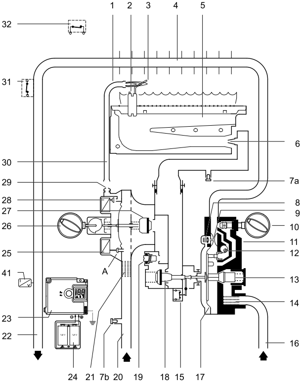
Fig. 2 Functional Diagram
7a Screw for measurement of pressure in burner
7b Screw for measurement of input pressure

Fig. 3 Electrical diagram
This gas heater is equipped with automatic electronic ignition which simplifies its operation.
After this procedure, automatic ignition occurs whenever a hot water tap is opened. First, the pilot burner is lit and approximately four seconds afterwards the main burner. The pilot burner flame is then extinguished after a short period of time.
This is a way of saving a great amount of energy as the pilot burner only operates for the minimum necessary time to ignite the main burner, in contrast to conventional systems which operate permanently.
Air in the gas supply pipe when the heater is started up may cause ignition to fail.
If this happens:
| Technical characteristics | Symbol | Units | WRD11 | WRD14 | WRD18 |
| Power and flow | |||||
| Nominal useful power | Pn | kW | 19,2 | 23,6 | 30,5 |
| Minimum useful power | Pmin | kW | 7 | 7 | 9 |
| Useful power (adjustment range) | kW | 7 - 19,2 | 7 - 23,6 | 7 - 30,5 | |
| Nominal thermal flow | Qn | kW | 21,8 | 27 | 34,5 |
| Minimum thermal flow | Qmin | kW | 8,1 | 8,1 | 10,3 |
| Gas data* | |||||
| Supply pressure | |||||
| Natural gas H | G20 | mbar | 20 | 20 | 20 |
| LPG (butane/propane) | G30/G31 | mbar | 30/37 | 30/37 | 30/37 |
| Consumption | |||||
| Natural gas H | G20 | m 3 /h | 2,3 | 2,9 | 3,7 |
| LPG (butane/propane) | G30/G31 | kg/h | 1,7 | 2,2 | 2,75 |
| Number of injectors | 12 | 14 | 18 | ||
| Water data | |||||
| Maximum permissible pressure** | pw | bar | 12 | 12 | 12 |
| Temperature selector in fully clockwise position | |||||
| Temperature rise | °C | 50 | 50 | 50 | |
| Flow range | l/min | 2 - 5,5 | 2 - 7 | 2 - 8,8 | |
| Minimum operating pressure | pwmin | bar | 0,1 | 0,1 | 0,2 |
| Minimum pressure for maximum flow | bar | 0,25 | 0,35 | 0,5 | |
| Temperature selector in fully anti-clockwise position | |||||
| Temperature rise | °C | 25 | 25 | 25 | |
| Flow range | l/min | 4 - 11 | 4 - 14 | 4 - 17,6 | |
| Minimum operating pressure | bar | 0,2 | 0,2 | 0,2 | |
| Minimum pressure for maximum flow | bar | 0,6 | 1 | 1,3 | |
| Combustion products*** | |||||
| Minimum low pressure | mbar | 0,015 | 0,015 | 0,015 | |
| Flow | g/s | 13 | 17 | 22 | |
| Temperature | °C | 160 | 170 | 180 | |
* Hi 15°C - 1013 mbar - dry: Natural gas 34.2 MJ/m3 (9.5 kWh/m3)
LPG: Butane 45.72 MJ/kg (12.7 kWh/kg) - Propane 46.44 MJ/kg (12.9 kWh/kg)
** Considering the water dilution effect this value must not be exceeded.
*** For nominal calorific power
Any local by-laws and regulations pertaining to installation and use of gas-heated appliances must be observed. Please refer to the laws that should be attended in your country.
The gas installation, the connection of exhaust/supply pipes as well as the initial startup are to be performed exclusively by authorised gas fitters.
The heater can only be used in the countries indicated on the rating plate.
In case of a frost risk:
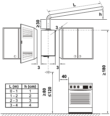
Ensure that the extremity of the evacuation pipe is placed between the ledge and the ring of the flue
If these conditions cannot be met, a different location must be selected for the gas intake and evacuation.
The maximum surface temperature of the heater is less than 85°C, with the exception of the combustion gases evacuation device. No special protection measures are required for flammable construction materials or built-in furniture items.
The place where the heater is to be installed must have an area of air supply according to the table.
| Heater | Minimum useful area |
| WRD11B | ≥60 cm 2 |
| WRD14B | ≥90 cm 2 |
| WRD18B | ≥120 cm 2 |
Tab. 5 Useful areas for air intake
The minimum requirements are listed above; however, each country's specified requirements must also be respected.
Never support the gas heater on the water or gas connections.
It is advisable to purge the installation beforehand, because the presence of dirt may reduce the flow and, in extreme cases, cause a blockage.
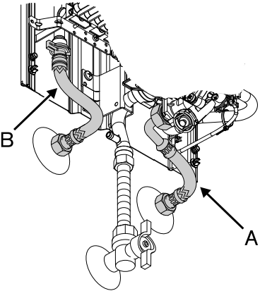
It is advisable to install a non-return valve on the supply side of the heater to avoid problems caused by sudden changes in supply pressure.
Any local by-laws and regulations pertaining to installation and use of gas-heated appliances must be observed.
Please refer to the laws that should be attended in your country.
Open all water and gas blocking devices. Purge the pipes.
The front panel in the burner and pilot burner area may reach high temperatures, with risk of burning in case of contact.
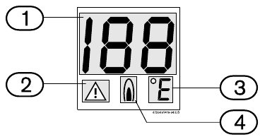
Fig. 6 Digital display
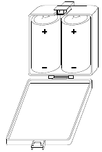
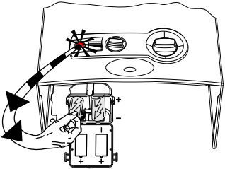
The batteries must be changed if the red LED starts flashing.
Fig. 8 Replacing the batteries
 , position
  .
. 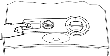
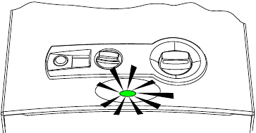
Green light on = Main burner on
Fig. 10
 , position
  .
.Lower water temperature.
Less power. 
Fig. 11
Higher water temperature.
More power. 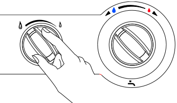
Fig. 12

Regulating the temperature to the minimum required value reduces energy consumption as well as the possibility of limescale deposits in the heat exchanger.
The temperature on the display is not precise, always check before bathing children or elderly people.
* Sealed elements must not be opened.
Heaters for natural gas (G 20) are supplied sealed from the factory after being adjusted to the values indicated on the rating plate.
Heaters must not be turned on if the coni nection pressure is lower than 15 mbar or higher than 25 mbar.
Heaters for propane/butane (G31/G30) are supplied sealed from the factory after being adjusted to the values indicated on the rating plate.
The following procedures must only be performed by a qualified technician.
It is possible to adjust the power using the burner pressure process, although a manometer is necessary for this procedure.

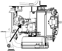
The minimum gas flow adjustment is performed automatically after the adjustment of the maximum gas flow.
| Natural gas H | Butane | Propane | ||
| Injector code | WR11 | 8708202113 (1,10) | 8708202130 (0,70) | |
| 8708202124 (1,20) | 8708202128 (0,72) | |||
| WR14 | 8708202113 (1,10) | 8708202128 (0,72) | ||
| 8708202116 (1,25) | 8708202132 (0,75) | |||
| WR18 | 8708202115 (1,15) | 8708202130 (0,70) | ||
| 8708202116 (1,25) | 8708202132 (0,75) | |||
| Connection pressure (mbar) | WR11 WR14 WR18 | 20 | 30 | 37 |
| MAX (mbar) | WR11 | 12,7 | 28 | 35 |
| WR14 | 12 | 28 | 35 | |
| WR18 | 10,3 | 25,5 | 32,5 | |
Tab. 6 Burner pressure
Only use the original conversion kits.
The conversion must only be performed by a qualified technician. The original conversion kits are supplied with assembly instructions.
Maintenance must only be performed by a qualified technician. After one or two years of use a general overhaul must be performed.
Before performing any maintenance work:
Without a water filter installed, turning on the heater is prohibited.
In case of a frost risk, proceed as follows:
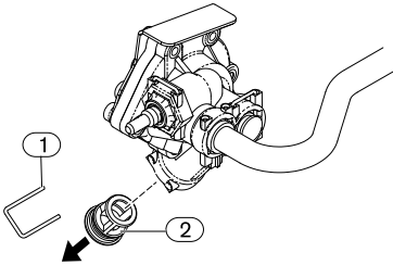
The probe must never be turned off, modified or replaced with a different part under any circumstances.
This probe verifies the conditions of flue evacuation and, in case of malfunction, it automatically turns off the heater. This prevents the combustion gases from entering the room where the gas heater has been installed. The probe restarts after a reset period.
If the heater turns off during operation:
The user must never touch the device.
If the probe malfunctions, proceed in the following manner:
To check the correct operation of the combustion gas probe, proceed in the following manner:
*Maintenance and Operating Check procedures must be performed by a qualified installer.
Assembly, maintenance and repairs must be performed by qualified technicians only. The following chart offers solutions to possible problems (solutions followed by an * must be undertaken by qualified technicians only).

Here you can download full pdf version of manual, it may contain additional safety instructions, warranty information, FCC rules, etc.
Do you have a question about the Junkers miniMAXX WR 11-2 B Series that isn't answered in the manual? Leave your question here.
Thank you! Your question has been received!